Tack för att du väljer produkter med hög kvalitet!
Du har produkten längre, har mer glädje av den, det är ekonomiskt och bättre för vår planet. Vi kommer att göra vårt bästa för snabb och säker leverans. Tveka inte att höra av dig om du har frågor.


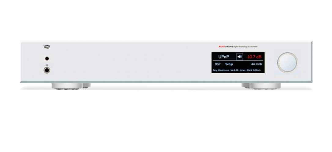
Weiss DAC501 / DAC502
DAC501 / DAC502 dsp d/a converter and network renderer
117,500kr – 127,500kr
Se alla betaltjänster:
KLARNA, DINTERO, PAYPAL, WASA
Önskar du rådgivning inför val av produkt?
Hör gärna av dig till oss!
The DAC501/DAC502 are our new state of the art D/A Converters with an unprecedented level of sophistication and versatily.
The DAC502 uses a larger frame but else sports the same features as the DAC501. Except for an an additional 4 pin headphone socket at the back of the unit.
With the DAC50x we are creating a new paradigm for what used to be a black box device. A typical D/A Converter is a "set and forget" device. Not so with the DAC50x. It adds a number of interesting signal processing features and sports a variety of digital inputs. Balanced, unbalanced and headphone outputs are provided.
Weiss Engineering has a 30 year history in D/A Converter design. In that time span we have learned a thing or two about converter design. The DAC50x is the essence of our experiences.
Mechanics
The DAC50x uses a stainless steel chassis with a solid 10 mm aluminium front plate.
Power Supply
A powerful non-switching power supply is used. All sensitive voltages have their own regulators which are separated between left and right channels. The result is an analog output free of “digital noise” and channel crosstalk. The power switch activates a semiconductor relay which only switches on or off at zero crossings of the mains voltage. This assures a glitch free power switching. The two mains transformers are toroidal types. Mains voltage selection is done automatically by measuring the mains voltage before power is applied to the rest of the electronics.
Synchronization
An internal high precision / low jitter clock generator is responsible for clocking the D/A converter section. The sampling frequency of that generator is fixed at about 195kHz. The input signals are converted to the 195kHz sampling frequency for optimal signal quality. This scheme also helps significantly in reducing any jitter related effects. All standard sampling frequencies up to 384 kHz plus DSD x64 and x128 are supported.
Digital Inputs
There are a total of five inputs:
AES/EBU or S/PDIF via XLR, Toslink and RCA sockets
UPnP / DLNA via Ethernet
USB
Accepted formats: PCM 44.1kHz up to 384 kHz, DSD 64x / 128x.
Future formats can be accommodated for via software updates.
- Signal Processing
The DAC50x has a digital signal processing chip built in (DSP).
The following DSP algorithms are currently implemented or implemented soon: - Room Equalizer - to suppress room modes for a decent bass reproduction.
- Creative Equalizer - a tone control with low boost/cut, high boost/cut and mid boost/cut. Very useful to correct those recordings which do not quite sound right.
- De-Essing - the automatic removal of overly bright sibilances from human voices. The sibilance effect can be more or less pronounced depending on your speakers or room acoustics.
- Constant Volume - adjusts the audio volume (loudness) to a constant value across all tracks played. Useful for "party mode" when the volume control should stay untouched.
- Vinyl Emulation - get that special sonic character of a record player based playback chain. We also employ an emulation of the DMM-CD procedure offered by the Stockfisch label.
- Crosstalk Cancelling (XTC) - for the playback of dummy head recordings or live recordings via speakers for an incredible live sensation. Dummy head recordings usually are listened to via headphones because they only work properly if the left channel goes to the left ear only and the right channel to the right ear only. With speakers this is difficult to achive as the left channel goes to the left and the right ear. But with some clever signal processing of the speaker channels is is possible to suppress the crosstalk, i.e. the audio going from the left speaker to the right ear and vice versa. If that works properly then the recording sounds as if one would be in the space where the recording has taken place. All the reverberation and 3D representation of the sound sources is there.(For speaker based playback only.)
- Out Of Head Localization algorithm - tries to get the music "out of your head" when listening via headphones. The goal is to achieve a similar listening sensation as one gets when listening via speakers.
(For headphone based playback only.)The following DSP algorithms are considered for implementation: - Roon streaming.
- MQA decoding.
- Airplay.
- Converters
- Two of the latest 32 bit D/A Converter chips are used. Two D/A conversion channels are used per audio channel, resulting in exceptional performance specifications.
Analog Outputs
Line out unbalanced on RCA connector
Line out balanced on XLR connector
Headphone out on 1/4" Jack Analogue
For the DAC502: Addtional headphone output on a 4 pin XLR connector.
Discrete output stages for both line and headphone outputs are employed.
The output levels can be set in a coarse manner with 4 steps to adapt for the amplifier or headphone connected. The levels can be set independently for line and headphone outputs.
No sound degrading servo mechanisms are used.
Front panel controls
A rotary encoder knob for changing parameters and for powering the unit on/off.
A touch screen colour LCD display.
An 1/4 inch headphone socket.
An IR receiver
Back panel elements
Analog outputs on XLR and RCA connectors.
Digital inputs on XLR, RCA, TOSLINK, USB, Ethernet connectors.
USB type A connector for various applications.
Mains connector with fuses.
IR Remote Control
Allows to control several functions of the DAC50x, namely:
The input selected for conversion.
The output type, level, muting, absolute polarity.
Power on/off.
DSP presets.
Web Interface
The DAC50x has a web interface for configuring it via a web browser. The following functions are accessible via the web interface:
Volume and Balance controls.
Input selection.
Output type.
DSP algorithms configuration.
DSP snapshots configuration.
DAC 502
Ytterligare information
| Color | Black, Silver |
|---|---|
| Specifications | Power Size DAC501 Size DAC502 Size Remote Available Color Digital Inputs Digital Outputs Analog Outputs
The output level is selectable via the LCD menu; four settings are provided as shown below: XLR Output: These levels are achieved with a 0.0 dB setting for the level control on the LCD screen. Suggested subsequent amplifier input impedances:
RCA Output: These levels are achieved with a 0.0 dB setting for the level control on the LCD screen. Suggested subsequent amplifier input impedances:
Headphone Output: 5.2 Vrms +16.53 dBu
Suggested headphone impedances: The same parameters apply to the 4 pin headphone output of the DAC502 as well. Synchronization
D/A Converter chip
Measurements Main Output
Frequency Response: Linearity: Spurious components (including harmonics): Crosstalk: Interchannel Phase Response: Frequency Response:
Total Harmonic Distortion plus Noise (THD+N): Linearity:
Spurious Components (including Harmonics):
Crosstalk:
Interchannel Phase Response: |
| Chassi | Weiss 501, Weiss 502 |
Reviews
Only logged in customers who have purchased this product may leave a review.
Teodor Sanden –
Click here to open the review on the Weiss 501 written by Alan Sircom- HIFI-Plus